3 phase SMS based motor controller is a product that can be used to control and monitor the status of a irrigation motor(can be used to control anything, but it was targeted to control irrigation motors).
The product specifications is listed below
- 3 Phase Motor Control
- 3 Phase voltage monitoring
- Current measurement along 1 phase line
- Dry run protection
- TCP based boot-loader
- Stats logging using TCP (IOT)
Below is a rant on what went into designing this board.
Motivation
This was mainly designed owing to my fathers pressure. We pump water to our farm from a far off place and owing to the huge amount of power outages, monitoring and controlling the motor is a huge burden. So in order to make this task less of a burden I started this design which started from a simple idea to almost a quality product.
Design
- I started the project during the end of my college, during which my knowledge of C programming was very poor. At that point my feeling was that Assembly programming was easier than C :).
- So this project started with me writing pages and pages of assembly code for Atmel based AVR128 micro-controller.
- After I started working in the industry, I became familiar with Arduino and other projects and I felt that assembly was difficult to maintain and I started rewriting the code in C.
Software
Let us split the software part of the system into multiple parts.
1. Boot loader
I needed a boot-loader for my system. For daily development and debugging nothing is better than the arduino boot-loader. But once the system was deployed in the field, I wanted a automated system in-order to provide updates and fix bugs. Since the board had GSM on it, using GPRS was the way to go. I then decided on using TCP based protocol in order to perform a Over the air programming (OTP) system for the device.
Once this system was implemented I felt that I should be able to track all the devices in the field and be able to see which devices are which version of the firmware. This meant I had to build a web application. Back then I choose to make use of PHP and the best options then were CodeIgnitor and CakePHP. I went ahead with CakePHP and built a website.
2. Main Application
I choose to write the application code from scratch rather then going ahead using arduino core. I have always felt that I have more control over the system when bare bones C code is used. During the whole process of building the code, I went through in two iterations. For the first time, I wrote without using any frameworks, but when I finished the first round of coding, I came across a UML based framework called Quantum Leaps for writing event driven code using UML based diagrams.
Event driven systems usually make you go crazy, when you start building event driven systems it is usually very difficult to create a picture in your brain. But luckily I got a quick boost and I would like to thank RicardoRaup for that.
GSM based systems usually have lots of AT commands which are usually strings and they usually tend to eat a lot of memory. This was true in my case too, so I had to optimize the usage of memory to fit in the whole code with lots of features and also make room for the boot-loader.
3. Features
I wanted to add a lot of features into the system in order to provide the user with more control, but in the end I had to make a call as to what I should include and what not. Some the features are listed below.
- Multiple user access with authentication
- System turn on and off
- System status monitoring with ability to set auto updates
- Posting system data to Xively
- Dry run protection
Hardware
The hardware design of the system went thought multiple iterations before it was frozen to go into production. So lets break the system into points.
- Power section: It first designed with a buck boost regulator. The GSM module consumes a lot of power in bursts, so design of the power system was crucial. But prototype designed had lots of noise issues, so I then decided to make use of two linear regulators from MICREL 29302 in order to generate multiple power rails +3v and +5v.
- Microcontroller: Since the prototype of the system was done using Arduino Uno, I choose to use ATMEGA328p in TQFP package. The controller runs at 16 Mhz.
- GSM: SIM900A from Simcom was used the GSM module in the system. This module is dual band module. This module has a RTC built in and I made use of this rather than adding one more component.
- Monitoring: The voltage monitoring section was built using resistor dividers and varistors were added for protection. In order to monitor the current along one phase, I used a current transformer.
Manufacturing
For designing the PCB for the system, I learnt a multitude of software’s owing to my stupidity. I stated with Eagle, but my company used OrCAD, so I switched. Later I found that Altium is very good too and again I switched and started from scratch. And finally I switched back again to Eagle.
For the prototype board, I went ahead and made them myself using home made ironing and ferric chloride based etching. After having etched so many boards, the practice made be capable of etching pcbs with traces as small as 5 mils. The results of this can be seen below.
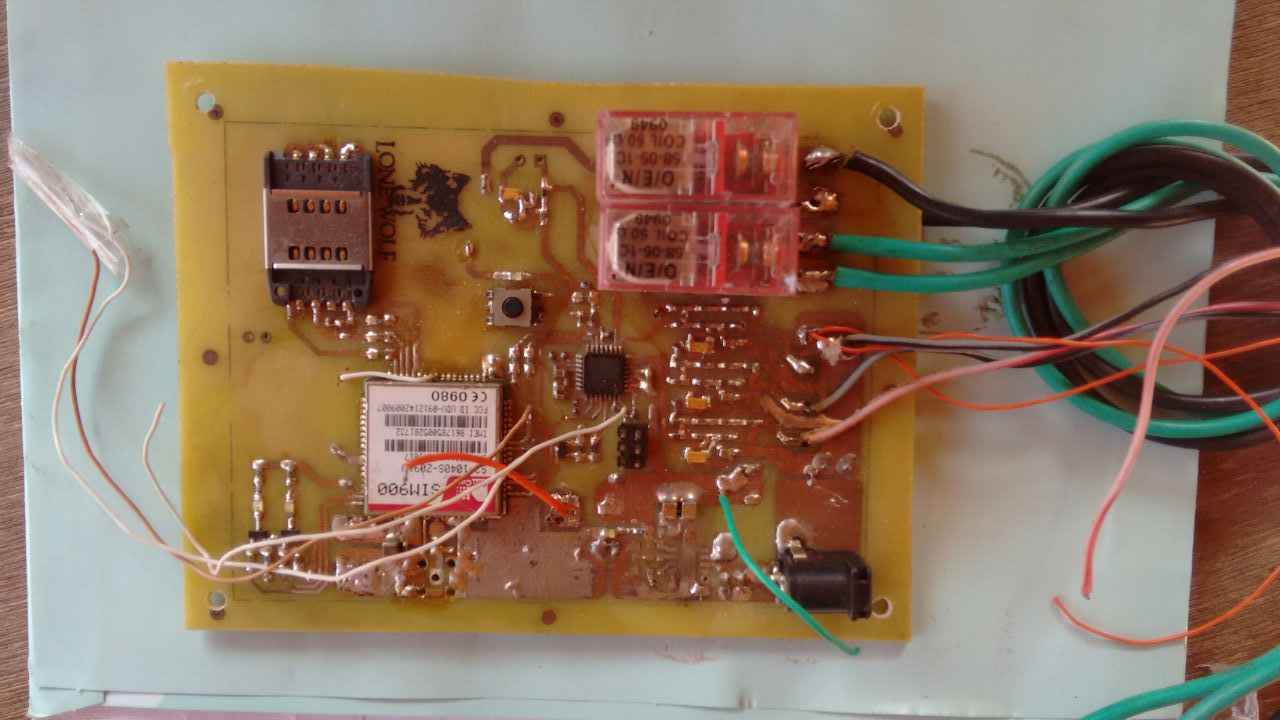
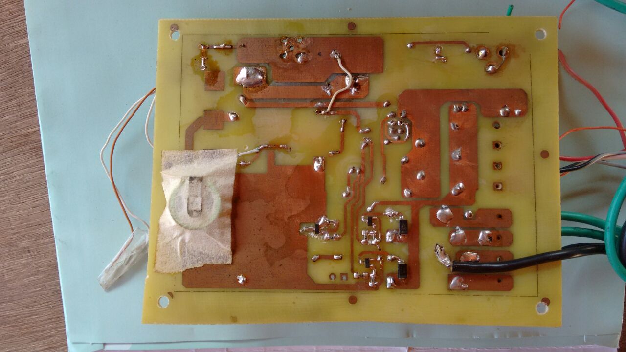
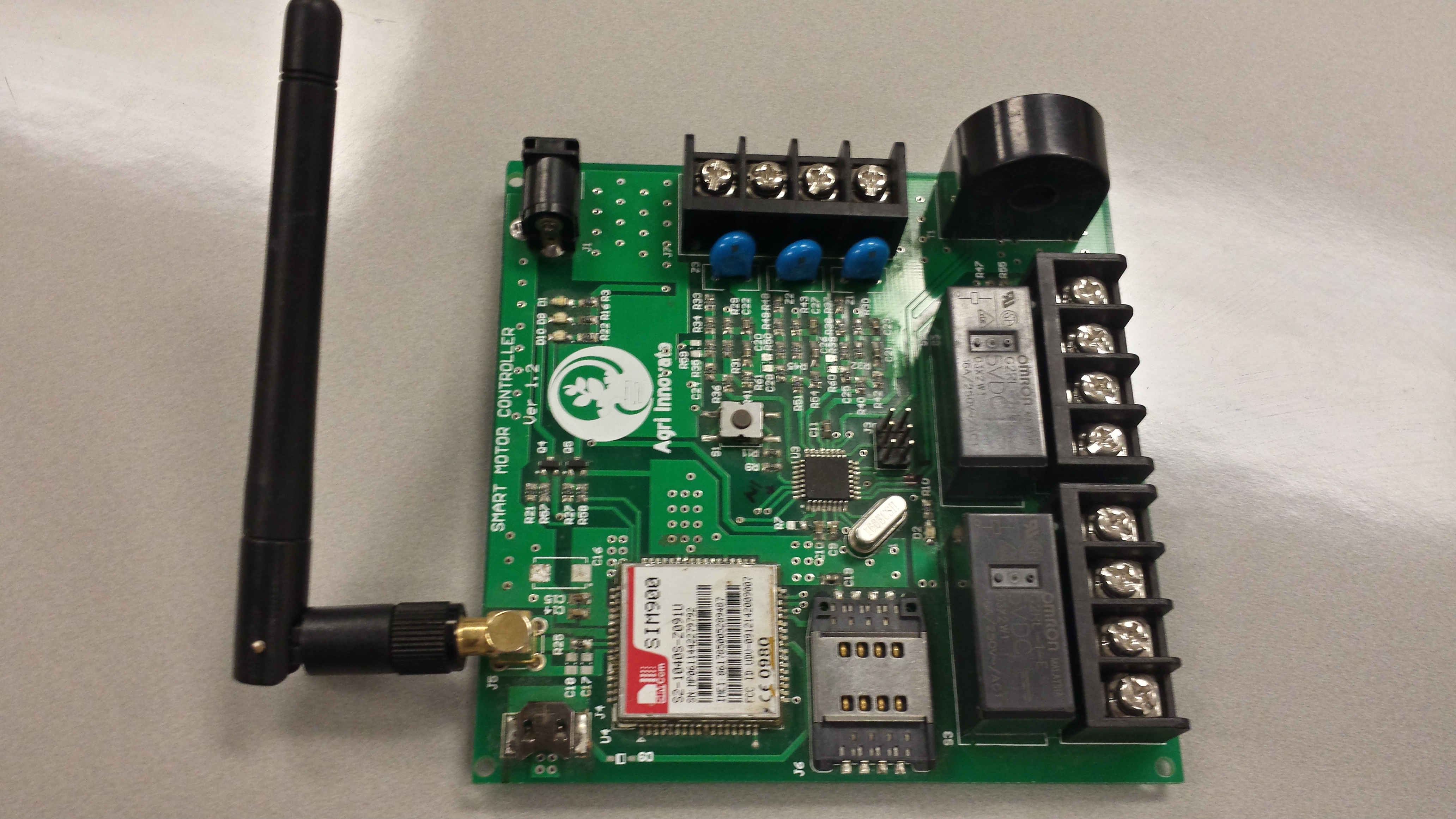
So when I was finally ready to go for production, I made use of Fusion PCB service of Seeedstudio to get them manufactured. The board had so many passives that hand soldering so many of them was a pain in the ass.
Name and Logo
After much brainstorming with my brother we decided on branding it as “AGRI INNOVATE”. I would also like to thank Niroop from IronJaw Studios for the logo.

Conclusion
This project was a very good experience for me. It gave me a perspective as to what goes into developing, producing and marketing a hardware based product. I got to understand the various facets of this process having gone through each of these be myself. The project has a lot of room for improvements. I would like to add more memory for the controller and better isolation between the mains if I decide on making one more revision. So this ends the long rant, thank you for your patience.