Power supply design is a crucial part of any circuit design. A USB power bank would provide the input for my design and the circuit required a constant voltage of 3.3v. The requirement was 5 - 5.5v to 3.3 - 3.6v. I needed a very efficient regulator capable of delivering very high current, as I 64 LED’s across two boards that needed to be powered. I am biased towards Texas Instruments and thus choose TPS62095.
TPS62095 is a very small (3mm x 3mm) step-down buck converter capable of supplying a current of 4A. It has a switching frequency of 1.4 MHz and an efficiency of 95%. It has an adjustable output voltage which you can configure using a resistor divider. But the problem is that it comes in a VQFN package.
Problems
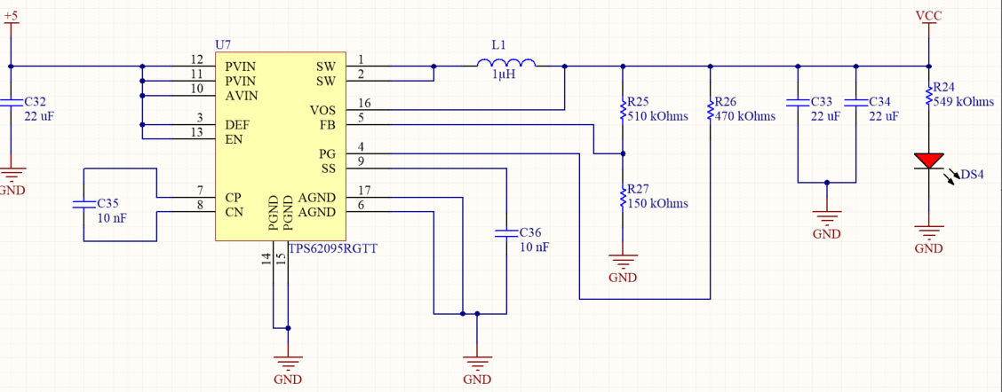
I had received the five boards, and I was excited about powering them up. I was aware that soldering the power IC was going to be difficult, but it developed into a huge problem. I tried two methods for soldering them, by hand and also using a stencil and an oven. But after both the methods, I was unsuccessful in getting the appropriate power from the circuit. I was of the opinion that the problem was in the soldering, and it is hard to check for bad solder joints as you cannot see the pads. The schematic and various imperfect waveforms are below.
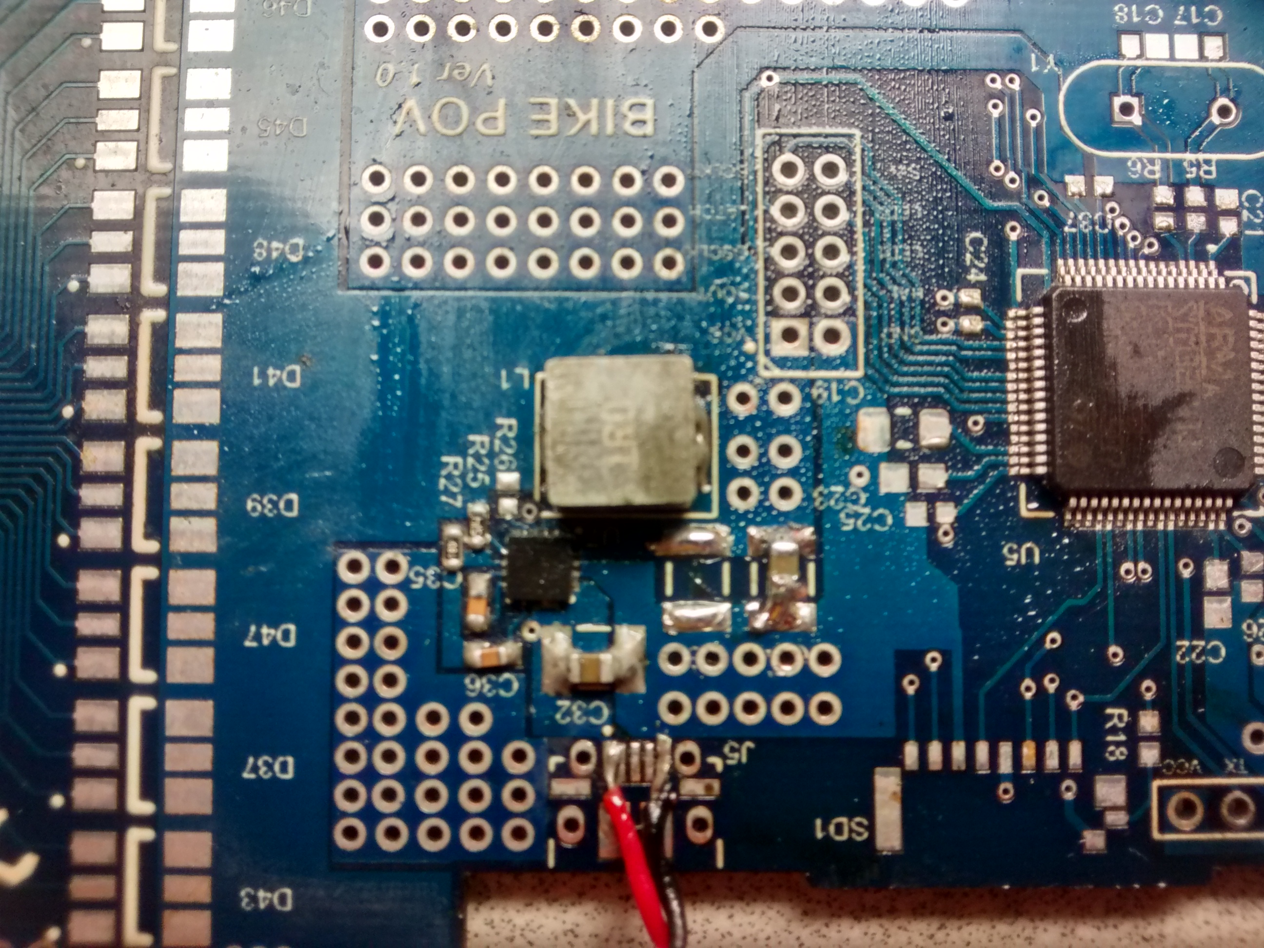
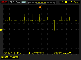
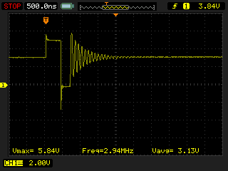
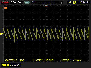
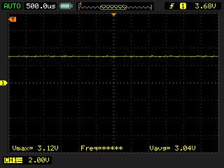
You can see that the output is at 3.12v, but the results were very inconsistent. I went on and destroyed four of five boards. I then joined hands with my Eddy who had a toaster for my final attempt at restoring the power. I was finally able to power the circuit. I have not yet soldered the rest of the parts, and I will let you know of the results, once I have completed.
